1. 개요
이 글에서 사용한 로버 프레임은 4WD Mecanum Wheel Kit 이다. 이 프레임에는 아두이노 328이 포함되어 있어, 동작 방식을 코딩 할 수 있다. 이 키트 프레임의 특징은 다음과 같다.
- 메카넘휠 특징상 몸체를 회전하지 않고, 좌우 및 대각선 방향 이동이 가능하다
- 몸체가 크게 흔들리지 않고 이동하며, 좁은 장소 이동에 유리하다
- 속도가 빠르지는 않으나, 무거운 물체를 안정적으로 옮길때 좋다
- 아두이노 기반 제어라, 개발 편의성과 확장성이 있다
- 바닥이 고른 곳이나 실내에 맞다

- 4WD Mecanum Wheel Kit
- Mecanum wheel robot - bluetooth controlled
- Vectoring robots with Omni or Mecanum wheels
- 4WD Mecanum Wheel Robot Kit Series
- Wheeled Mobile Robot Development Platforms - From Budget to Full-Featured
- Nexus Robot Kits & Supplies
- Nexus robot user manual
- 2x RF communication APC220A Modules TTL for Arduino
관련 사이트에는 다음과 같이, 개발에 필요한 기본 코드 등을 제공하고 있다.
570.9KB

610.3KB
61.5KB
1.4KB
2. 로버 제어 코드 업로드
로버 제어를 위해 제공되는 Nexus Automation 10021 Library Files에는 샘플파일이 포함되어 있다. 이를 이용해 로버 제어 코드를 개발하기 위해서는 몇가지 사전 준비가 필요하다.
1. Arduino IDE 1.0.4 다운로드 및 설치: 최신 아두이노 IDE 프로그램은 이 로버에 포함되어 있는 Arduino 328과 호환되지 않는다. 그래서, 오래된 버전을 사용해야 한다.
2. RS485 점퍼 제거: 아두이노 IDE에서 개발된 코드를 Arduino 328 보드에 전송하려면, 다음 그림의 아두이노 입출력 확장 보드의 RS485 점퍼를 제거해야 한다.

구글링을 통해, Arduino 포럼에서 점퍼가 다음 적색 박스에 있다는 것을 확인하였으나, 정확한 위치가 표시되어 있지는 않았다. 해당 점퍼를 제대로 제거하지 않으면, 코드가 전송되지 않는다.


할 수없이 무한조합을 통해, 다음과 같이 점퍼가 세팅되어 있을 때 코드가 제대로 보드에 업로드된다는 것을 확인하였다.

3. Arduino IDE의 Arduino Duemilanove w/ ATmega328 설정: IDE에서 호환보드로 Arduino Duemilanove w/ ATmega328 를 다음 그림과 같이 설정해야 한다.

3. 로버 제어 코드 분석
로버 제어를 위해 제공되는 Nexus Automation 10021 Library Files에는 샘플파일이 포함되어 있다. 이를 이용해 로버 제어 코드를 개발하기 위해서는 몇가지 사전 준비가 필요하다.
1. Arduino IDE 1.0.4 다운로드 및 설치: 최신 아두이노 IDE 프로그램은 이 로버에 포함되어 있는 Arduino 328과 호환되지 않는다. 그래서, 오래된 버전을 사용해야 한다.
2. RS485 점퍼 제거: 아두이노 IDE에서 개발된 코드를 Arduino 328 보드에 전송하려면, 다음 그림의 아두이노 입출력 확장 보드의 RS485 점퍼를 제거해야 한다.

구글링을 통해, Arduino 포럼에서 점퍼가 다음 적색 박스에 있다는 것을 확인하였으나, 정확한 위치가 표시되어 있지는 않았다. 해당 점퍼를 제대로 제거하지 않으면, 코드가 전송되지 않는다.

RS485 점퍼들
할 수없이 무한조합을 통해, 다음과 같이 점퍼가 세팅되어 있을 때 코드가 제대로 보드에 업로드된다는 것을 확인하였다.

RS485 점퍼는 바로 앞 그림 속의 3개 점퍼 중 맨 위에 있는 것임
3. Arduino IDE의 Arduino Duemilanove w/ ATmega328 설정: IDE에서 호환보드로 Arduino Duemilanove w/ ATmega328 를 다음 그림과 같이 설정해야 한다.

3. 로버 제어 코드 분석
로버 제어에 사용되는 라이브러리는 다음과 같이 구성되어 있다.
로버 제어 메인 코드는 다음과 같다.
#include <PinChangeInt.h>
#include <PinChangeIntConfig.h>
#include <EEPROM.h>
#define _NAMIKI_MOTOR //for Namiki 22CL-103501PG80:1
#include <fuzzy_table.h>
#include <PID_Beta6.h>
#include <MotorWheel.h>
#include <Omni4WD.h>
#include <fuzzy_table.h>
#include <PID_Beta6.h>
irqISR(irq1,isr1);
MotorWheel wheel1(3,2,4,5,&irq1);
irqISR(irq2,isr2);
MotorWheel wheel2(11,12,14,15,&irq2);
irqISR(irq3,isr3);
MotorWheel wheel3(9,8,16,17,&irq3);
irqISR(irq4,isr4);
MotorWheel wheel4(10,7,18,19,&irq4);
Omni4WD Omni(&wheel1,&wheel2,&wheel3,&wheel4);
void setup() {
//TCCR0B=TCCR0B&0xf8|0x01; // warning!! it will change millis()
TCCR1B=TCCR1B&0xf8|0x01; // Pin9,Pin10 PWM 31250Hz
TCCR2B=TCCR2B&0xf8|0x01; // Pin3,Pin11 PWM 31250Hz
Omni.PIDEnable(0.31,0.01,0,10);
}
void loop() {
// Omni.demoActions(100,1500,500,false);
}
순서는 다음과 같다.
1. 각 바퀴(MotorWheel) 객체 별로 PWM, Dir, IRQ(interrupt request), ISR(interrupt service routine) 을 설정한다.
2. 각 바퀴 객체를 Omni4WD 객체에 설정한다.
3. setup() 함수에서 메카넘 휠 제어를 위한 PID 값을 설정한다.
- EEPROM: EEPROM에 데이터를 읽고 쓴다.
- Firmata
- MotorWheel: Motor wheel을 제어한다.
- PID_Beta6: PID계산을 수행한다.
- PinChangeInt: 아두이노 인터럽트 지원을 위한 확장 라이브러리이다.
- Wire: TWI/I2C 라이브러리이다.
로버 제어 메인 코드는 다음과 같다.
#include <PinChangeInt.h>
#include <PinChangeIntConfig.h>
#include <EEPROM.h>
#define _NAMIKI_MOTOR //for Namiki 22CL-103501PG80:1
#include <fuzzy_table.h>
#include <PID_Beta6.h>
#include <MotorWheel.h>
#include <Omni4WD.h>
#include <fuzzy_table.h>
#include <PID_Beta6.h>
irqISR(irq1,isr1);
MotorWheel wheel1(3,2,4,5,&irq1);
irqISR(irq2,isr2);
MotorWheel wheel2(11,12,14,15,&irq2);
irqISR(irq3,isr3);
MotorWheel wheel3(9,8,16,17,&irq3);
irqISR(irq4,isr4);
MotorWheel wheel4(10,7,18,19,&irq4);
Omni4WD Omni(&wheel1,&wheel2,&wheel3,&wheel4);
void setup() {
//TCCR0B=TCCR0B&0xf8|0x01; // warning!! it will change millis()
TCCR1B=TCCR1B&0xf8|0x01; // Pin9,Pin10 PWM 31250Hz
TCCR2B=TCCR2B&0xf8|0x01; // Pin3,Pin11 PWM 31250Hz
Omni.PIDEnable(0.31,0.01,0,10);
}
void loop() {
// Omni.demoActions(100,1500,500,false);
}
1. 각 바퀴(MotorWheel) 객체 별로 PWM, Dir, IRQ(interrupt request), ISR(interrupt service routine) 을 설정한다.
2. 각 바퀴 객체를 Omni4WD 객체에 설정한다.
3. setup() 함수에서 메카넘 휠 제어를 위한 PID 값을 설정한다.
4. loop() 함수에서 demo 동작을 수행한다.
각 바퀴를 제어하는 것은 Omni4WD 객체이다. 객체의 클래스 멤버는 다음과 같다.
Omni4WD(MotorWheel* wheelUL,MotorWheel* wheelLL,
MotorWheel* wheelLR,MotorWheel* wheelUR,unsigned int wheelspan=WHEELSPAN);
unsigned char switchMotors();
unsigned char switchMotorsReset();
unsigned int setMotorAll(unsigned int speedMMPS=0,bool dir=DIR_ADVANCE);
unsigned int setMotorAllStop();
unsigned int setMotorAllAdvance(unsigned int speedMMPS=0);
unsigned int setMotorAllBackoff(unsigned int speedMMPS=0);
unsigned int setCarStop(unsigned int ms=0);
int setCarMove(int speedMMPS,float rad,float omega=0);
int setCarAdvance(int speedMMPS=0);
int setCarBackoff(int speedMMPS=0);
int setCarLeft(int speedMMPS=0);
int setCarRight(int speedMMPS=0);
float setCarRotate(float omega);
int setCarRotateLeft(int speedMMPS=0);
int setCarRotateRight(int speedMMPS=0);
int setCarUpperLeft(int speedMMPS=0);
int setCarLowerLeft(int speedMMPS=0);
int setCarUpperRight(int speedMMPS=0);
int setCarLowerRight(int speedMMPS=0);
float getCarSpeedRad() const;
int getCarSpeedMMPS() const;
int setCarSpeedMMPS(int speedMMPS=0,unsigned int ms=1000);
int setCarSlow2Stop(unsigned int ms=1000);
int wheelULGetSpeedMMPS() const;
unsigned int wheelULSetSpeedMMPS(unsigned int speedMMPS,bool dir);
int wheelULSetSpeedMMPS(int speedMMPS);
int wheelLLGetSpeedMMPS() const;
unsigned int wheelLLSetSpeedMMPS(unsigned int speedMMPS,bool dir);
int wheelLLSetSpeedMMPS(int speedMMPS);
int wheelURGetSpeedMMPS() const;
unsigned int wheelURSetSpeedMMPS(unsigned int speedMMPS,bool dir);
int wheelURSetSpeedMMPS(int speedMMPS);
int wheelLRGetSpeedMMPS() const;
unsigned int wheelLRSetSpeedMMPS(unsigned int speedMMPS,bool dir);
int wheelLRSetSpeedMMPS(int speedMMPS);
bool PIDEnable(float kc=KC,float taui=TAUI,float taud=TAUD,unsigned int interval=1000);
bool PIDDisable(); // 201209
bool PIDGetStatus(); // 201209
float PIDGetP_Param(); // 201210
float PIDGetI_Param(); // 201210
float PIDGetD_Param(); // 201210
bool PIDRegulate();
void delayMS(unsigned int ms=100, bool debug=false,unsigned char* actBreak = 0);
void demoActions(unsigned int speedMMPS=100,unsigned int duration=5000,unsigned int uptime=500,bool debug=false);
이 중에 demoActions()함수가 데모 동작 제어를 하는 멤버이다. 이 함수를 좀 더 분석해 보자.
void Omni4WD::demoActions(unsigned int speedMMPS,unsigned int duration,
unsigned int uptime,bool debug)
{
// 데모 동작을 위한 함수 포인트 배열 설정. 차례대로, 전진, 후진, 좌로 이동, 우로 이동, 좌상단, 우하단
// 좌하단, 우상단, 좌회전, 우회전 함수로 구성되어 있다.
int (Omni4WD::*carAction[])(int speedMMPS)={
&Omni4WD::setCarAdvance,
&Omni4WD::setCarBackoff,
&Omni4WD::setCarLeft,
&Omni4WD::setCarRight,
&Omni4WD::setCarUpperLeft,
&Omni4WD::setCarLowerRight,
&Omni4WD::setCarLowerLeft,
&Omni4WD::setCarUpperRight,
&Omni4WD::setCarRotateLeft,
&Omni4WD::setCarRotateRight
};
// 각 함수 포인트를 호출하고, 잠시 딜레이를 준다 (데모에서 호출된 시간은 1.5초이므로,
// 이 시간 동안, 각 함수 기능이 수행된다.
for(int i=0;i<10;++i) {
(this->*carAction[i])(0); // default parameters not available in function pointer
setCarSpeedMMPS(speedMMPS, uptime);
delayMS(duration, debug);
setCarSlow2Stop(uptime); // 다음 동작 전에 천천히 멈춘다. 데모는 0.5초 동안이다.
}
setCarStop(); // 완전히 멈춘다.
delayMS(duration); // 지연을 둔다. 데모는 1.5초이다.
}
4. 로버 제어 동작 제어
로버 제어 코드는 다음과 같다.
이제 로버를 제어하는 주요 함수의 기능을 파악했으니, 간단히, 로버를 1.5초 직진한 후, 좌측으로 1.5초 이동해, 1.5초 멈추고, 다시 원 위치로 오는 동작을 코딩해 보자.
void loop() {
// 각 함수 포인트를 호출하고, 잠시 딜레이를 준다 (데모에서 호출된 시간은 1.5초이므로,
// 이 시간 동안, 각 함수 기능이 수행된다.
unsigned int speedMMPS = 100;
unsigned int duration = 1500;
unsigned int uptime = 500;
bool debug = false;
for(int i=0; i < 4; ++i)
{
if(i == 0)
Omni.setCarAdvance(0);
else if(i == 1)
Omni.setCarLeft(0);
else if(i == 2)
Omni.setCarRight(0);
else
Omni.setCarBackoff(0);
Omni.setCarSpeedMMPS(speedMMPS, uptime);
Omni.delayMS(duration, debug);
Omni.setCarSlow2Stop(uptime); // 다음 동작 전에 천천히 멈춘다. 데모는 0.5초 동안이다.
}
Omni.setCarStop(); // 완전히 멈춘다.
Omni.delayMS(duration); // 지연을 둔다. 데모는 1.5초이다.
}
이제 앞에처럼, 코딩한 것을 로버에 전송해 본다. 그리고, 로버의 파워 버튼을 눌러 본다. 다음과 같이 동작되면, 성공한 것이다.
5. 로버 무선 제어
로버 무선 제어를 위해, 아두이노 확장 보드에 있는 Bluetooth 무선 통신 핀을 사용해 보자. 확장보드의 재원은 다음 링크를 참고한다.
사실, 이 확장보드 사용방법은 그리 친절하지 않다. 블루투스 통신을 위해서는 우선 HC-06같은 블루투스 통신 장치가 있어야 하며, 통신 속도 등을 미리 설정해 놓어야 한다. 이 경우에는 AT+BAUD8 명령으로 최고속도로 설정해 놓고, 아두이노 보드에서 시리얼 통신으로 정상 설정되었는 지 등을 여러번 테스트해 보는 과정을 거쳤다.
이제, 블루투스 통신 장치의 이름, 속도(115200), 암호(보통은 1234임) 등이 제대로 확인되었다면, 다음과 같은 순서로 로버 무선 통신을 개발해본다.
1. 다음과 같이 코딩하여, 로버의 아두이노 보드에 전송한다. 로버 컨트롤 코딩은 매우 간단하게, g(go), back(b), left(l), right(r), t1(turn left), t2(turn right)로 하였다.
2. 확장보드의 APC 220/Bluetooth 핀을 본인이 가지고 있는 블루투스 송수신 장치와 연결
확장보드의 해당 핀들 중 RX, TX, VCC, GND만 연결하면 된다.
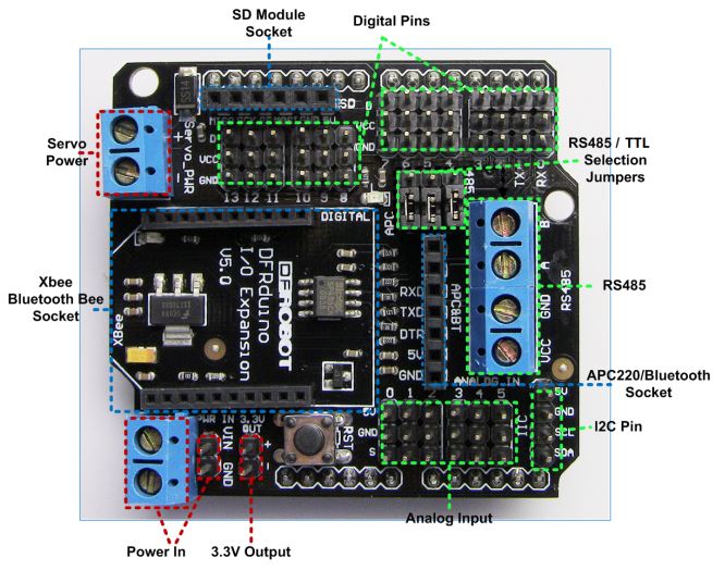
HC-06 블루투스의 경우, RX, TX, VCC, GND가 있으며, VCC, GND는 같은 핀에 연결하고, RX, TX만 서로 바꾸어 연결한다.
VCC - VCC
GND - GND
RX - TX
TX - RX

3. Bluetooth Terminal 앱을 안드로이드 폰이나 스마트 패드에 설치하고, 앞에서 연결한 블루투스와 페어링한 후, 이 앱을 실행해, 연결하고, 글자를 입력하여 테스트해본다. 정상적이면, 다음과 같이 무선으로 로버를 조정할 수 있다.
테스트를 위해, 블루투스 통신이 어렵도록 문을 닫고 테스트를 해 본다던지, 원거리에서 테스트해 보는 등의 과정을 거쳤으나, 큰 문제 없이 잘 동작된다. 보통, 블루투스는 탁 트인곳에서 20미터에서 최대 30미터까지 통신이 가능하다. 물론, 블루투스 통신이 많은 환경에서는 이름, 암호 등은 다르게 설정해야 혼선이 없다.
이제 로버에 무선 통신을 이용해 다양한 명령을 줄 수 있으니, 로버에 마운팅된 센서에서 데이터를 받거나, 액추에이터를 제어할 수 있다. 다만, 대용량 데이터가 필요한 센서의 경우에는 WiFi 등 좀 더 대역폭이 좋은 무선 통신 방식을 사용해야 한다.
다음 영상은 작업자가 진입하기 어려운 공간의 3차원 이미지 스캔을 위해 트림블사의 스캐너를 이 로버와 마운팅해 테스트한 영상이다.


이 글에서 사용된 로버의 제어 보드는 스펙이 좀 오래된 것이라, 점퍼 등 정확한 제원을 찾기가 어려웠다. 하지만, 가성비가 높고, 메카넘휠이 추가되어 있어, 안정적으로 이동하는 로버를 개발할 수 있다. 아울러, 많은 아두이노 라이브러리를 이용해, 센서와 연동하면, 더 강력한 로버를 개발할 수 있다는 점은 확장성 면에서 큰 장점이다.
void loop() {
// 각 함수 포인트를 호출하고, 잠시 딜레이를 준다 (데모에서 호출된 시간은 1.5초이므로,
// 이 시간 동안, 각 함수 기능이 수행된다.
unsigned int speedMMPS = 100;
unsigned int duration = 1500;
unsigned int uptime = 500;
bool debug = false;
for(int i=0; i < 4; ++i)
{
if(i == 0)
Omni.setCarAdvance(0);
else if(i == 1)
Omni.setCarLeft(0);
else if(i == 2)
Omni.setCarRight(0);
else
Omni.setCarBackoff(0);
Omni.setCarSpeedMMPS(speedMMPS, uptime);
Omni.delayMS(duration, debug);
Omni.setCarSlow2Stop(uptime); // 다음 동작 전에 천천히 멈춘다. 데모는 0.5초 동안이다.
}
Omni.setCarStop(); // 완전히 멈춘다.
Omni.delayMS(duration); // 지연을 둔다. 데모는 1.5초이다.
}
이제 앞에처럼, 코딩한 것을 로버에 전송해 본다. 그리고, 로버의 파워 버튼을 눌러 본다. 다음과 같이 동작되면, 성공한 것이다.
로버 무선 제어를 위해, 아두이노 확장 보드에 있는 Bluetooth 무선 통신 핀을 사용해 보자. 확장보드의 재원은 다음 링크를 참고한다.
사실, 이 확장보드 사용방법은 그리 친절하지 않다. 블루투스 통신을 위해서는 우선 HC-06같은 블루투스 통신 장치가 있어야 하며, 통신 속도 등을 미리 설정해 놓어야 한다. 이 경우에는 AT+BAUD8 명령으로 최고속도로 설정해 놓고, 아두이노 보드에서 시리얼 통신으로 정상 설정되었는 지 등을 여러번 테스트해 보는 과정을 거쳤다.
이제, 블루투스 통신 장치의 이름, 속도(115200), 암호(보통은 1234임) 등이 제대로 확인되었다면, 다음과 같은 순서로 로버 무선 통신을 개발해본다.
1. 다음과 같이 코딩하여, 로버의 아두이노 보드에 전송한다. 로버 컨트롤 코딩은 매우 간단하게, g(go), back(b), left(l), right(r), t1(turn left), t2(turn right)로 하였다.
#include <PinChangeInt.h>
#include <PinChangeIntConfig.h>
#include <EEPROM.h>
#define _NAMIKI_MOTOR //for Namiki 22CL-103501PG80:1
#include <fuzzy_table.h>
#include <PID_Beta6.h>
#include <MotorWheel.h>
#include <Omni4WD.h>
#include <fuzzy_table.h>
#include <PID_Beta6.h>
// #include <SoftwareSerial.h>
// SoftwareSerial mySerial(10, 11); // RX, TX
irqISR(irq1,isr1);
MotorWheel wheel1(3,2,4,5,&irq1);
irqISR(irq2,isr2);
MotorWheel wheel2(11,12,14,15,&irq2);
irqISR(irq3,isr3);
MotorWheel wheel3(9,8,16,17,&irq3);
irqISR(irq4,isr4);
MotorWheel wheel4(10,7,18,19,&irq4);
Omni4WD Omni(&wheel1,&wheel2,&wheel3,&wheel4);
boolean toggle = false;
void toggleLED()
{
if(toggle == false)
digitalWrite(13, HIGH);
else
digitalWrite(13, LOW);
toggle = toggle ? false : true;
}
void setup() {
//TCCR0B=TCCR0B&0xf8|0x01; // warning!! it will change millis()
TCCR1B=TCCR1B&0xf8|0x01; // Pin9,Pin10 PWM 31250Hz
TCCR2B=TCCR2B&0xf8|0x01; // Pin3,Pin11 PWM 31250Hz
Omni.PIDEnable(0.31,0.01,0,10);
Serial.begin(115200);
pinMode(13, OUTPUT);
}
void loop() {
// Omni.demoActions(100,1500,500,false);
char val = 0;
char string[256];
int i = 0;
while(Serial.available())
{
char ch = Serial.read();
string[i] = ch;
i++;
if(ch == -1)
break;
delay(5);
}
string[i] = 0;
unsigned int speedMMPS = 100;
unsigned int duration = 1000;
unsigned int uptime = 500;
bool debug = false;
if(strstr(string, "g"))
{
Omni.setCarAdvance(0);
Omni.setCarSpeedMMPS(speedMMPS, uptime);
Omni.delayMS(duration, debug);
Omni.setCarSlow2Stop(uptime);
}
else if(strstr(string, "b"))
{
Omni.setCarBackoff(0);
Omni.setCarSpeedMMPS(speedMMPS, uptime);
Omni.delayMS(duration, debug);
Omni.setCarSlow2Stop(uptime);
}
else if(strstr(string, "l"))
{
Omni.setCarLeft(0);
Omni.setCarSpeedMMPS(speedMMPS, uptime);
Omni.delayMS(duration, debug);
Omni.setCarSlow2Stop(uptime);
}
else if(strstr(string, "r"))
{
Omni.setCarRight(0);
Omni.setCarSpeedMMPS(speedMMPS, uptime);
Omni.delayMS(duration, debug);
Omni.setCarSlow2Stop(uptime);
}
else if(strstr(string, "t1"))
{
Omni.setCarRotate(0);
Omni.setCarRotateLeft(speedMMPS);
Omni.delayMS(duration, debug);
Omni.setCarSlow2Stop(uptime);
}
else if(strstr(string, "t2"))
{
Omni.setCarRotate(0);
Omni.setCarRotateRight(speedMMPS);
Omni.delayMS(duration, debug);
Omni.setCarSlow2Stop(uptime);
}
else if(strstr(string, "t"))
{
toggleLED();
}
Omni.setCarStop(); // 완전히 멈춘다.
Omni.delayMS(duration); // 지연을 둔다. 데모는 1.5초이다.
}
확장보드의 해당 핀들 중 RX, TX, VCC, GND만 연결하면 된다.
HC-06 블루투스의 경우, RX, TX, VCC, GND가 있으며, VCC, GND는 같은 핀에 연결하고, RX, TX만 서로 바꾸어 연결한다.
VCC - VCC
GND - GND
RX - TX
TX - RX

로버에 블루투스를 연결 모습
3. Bluetooth Terminal 앱을 안드로이드 폰이나 스마트 패드에 설치하고, 앞에서 연결한 블루투스와 페어링한 후, 이 앱을 실행해, 연결하고, 글자를 입력하여 테스트해본다. 정상적이면, 다음과 같이 무선으로 로버를 조정할 수 있다.
블루투스 무선 기반 로버 제어 테스트 화면
테스트를 위해, 블루투스 통신이 어렵도록 문을 닫고 테스트를 해 본다던지, 원거리에서 테스트해 보는 등의 과정을 거쳤으나, 큰 문제 없이 잘 동작된다. 보통, 블루투스는 탁 트인곳에서 20미터에서 최대 30미터까지 통신이 가능하다. 물론, 블루투스 통신이 많은 환경에서는 이름, 암호 등은 다르게 설정해야 혼선이 없다.
이제 로버에 무선 통신을 이용해 다양한 명령을 줄 수 있으니, 로버에 마운팅된 센서에서 데이터를 받거나, 액추에이터를 제어할 수 있다. 다만, 대용량 데이터가 필요한 센서의 경우에는 WiFi 등 좀 더 대역폭이 좋은 무선 통신 방식을 사용해야 한다.
다음 영상은 작업자가 진입하기 어려운 공간의 3차원 이미지 스캔을 위해 트림블사의 스캐너를 이 로버와 마운팅해 테스트한 영상이다.
3차원 이미지 스캔 기반 Inspection rover


로버 기반 3차원 이미지 스캐닝 결과
6. 마무리
댓글 없음:
댓글 쓰기